
- #Diptrace pcb layout manual update
- #Diptrace pcb layout manual manual
- #Diptrace pcb layout manual software
- #Diptrace pcb layout manual trial
Hope this tutorial will give you a quick start on DipTrace. Now you can export or print your PCBs using the options given the File Menu.
#Diptrace pcb layout manual update
Right Click on Copper pour border > Update (Generally 6mm outer diameter and 4mm inner diameter).

#Diptrace pcb layout manual manual
facilitating circuit board designing activities through manual routing of. Place mounting hole in each corner of the PCB design and you can edit it dimensions by right clicking on it. DipTrace is a schematic and printed circuit board (PCB) design software.
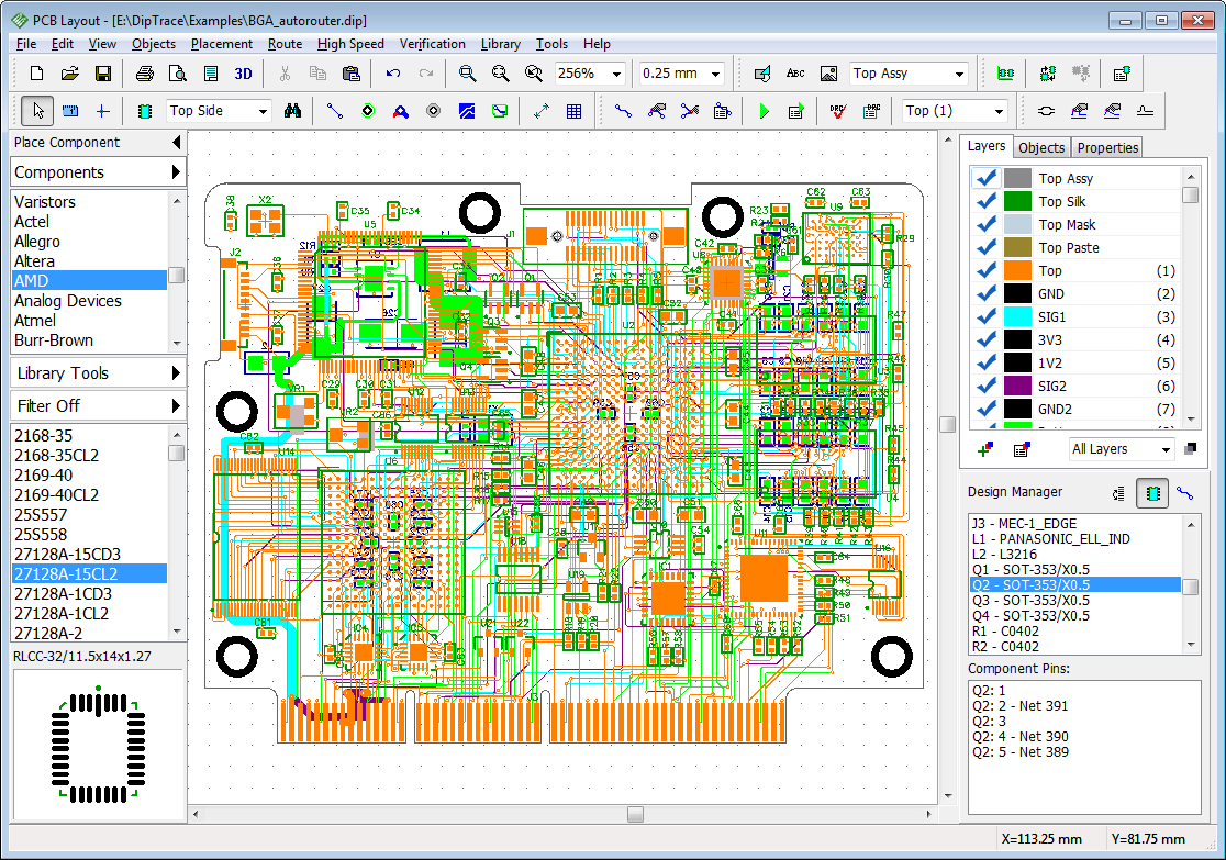
Next step is to add Mounting Hole, for that select Objects > Place Mounting Hole. In the connectivity option, select the net (Usually Ground net) in the Connect to Net and Thermals as 4 spoke. (Net name of a particular Pad or Trace can be find by right clicking on it). Then draw border of the PCB around the components and press enter after completing. Firstly Select Bottom Layer as given above. Copper Pour reduces noises, makes etching easy and provide strength to PCB. Next step is to add Copper Pour to PCB. Use this Drop Menu to Switch Layers – DipTrace After Routing is complete, top view and bottom view. To autoroute the PCB click Route > Run Autorouter. To set conductive trace width and trace clearance, go to Route > Route Setup.ĭiptrace Route Setup – Trace Width and Clearence. Mark Bottom Layer as Signal and Top as Plane. Go to Route option in menu bar and select Layer Setup. Here we need only Single Sided PCB (Copper conductive track on one side and Components on the other side). You can adjust the Solder Pad sizes such that you can properly solder it. Arrange the components so that they occupy minimum space. Then import it to PCB Layout by pressing Ctrl+B or select File > Convert to PCB. After drawing the circuit, Save the Schematic. Wire the simple circuit to glow an LED. Here also you should make sure that Pattern / Footprint is linked with the component at the bottom left column. You can also place the component from a particular library as follows. Then click the Place button to add that component to Worksheet. Make sure that Pattern (Footprint) is linked with the component you are using by clicking on the Pattern button. You can use the Find Component tool in the Objects menu for finding and placing components. Select Schematic Capture from the Launcher. #Diptrace pcb layout manual trial
In this section we will start learning DipTrace by designing a small trial PCB. After completing the circuit diagrams, these are converted into PCB by using PCB Layout. The PCB Layout enables us to manually / automatically place components and route conductive tracks. Circuit Diagrams can be drawn in Schematic Capture.

Component Editor is for defining Symbol while Pattern Editor is for creating its Footprint. Unlimited board size is supported.In these Component Editor and Pattern Editor allows us to create new components. Use the intelligent manual routing tools to finish the design and to get the best results you want. Autorouter achieves extremely high completion rates by going back and re-routing nets to make space for connections that could not be routed on a previous pass. Available with a “rip-up and retry” algorithm.
#Diptrace pcb layout manual software
When you create or edit design objects they are highlighted to improve your work.Įasy to use manual and powerful automatic routingĭipTrace pcb software includes an advanced automatic router that is able to route single-layer and multi-layer boards. Then select the menu option “Convert to PCB” to convert the schematic to PCB layout.

To design a schematic, simply select and place components onto your document and connect them together using the wire and bus tools of schematic capture program.
Component Editor - allows you to draw parts and make components. Pattern Editor - allows you to create part footprints. Schematic - Schematic Capture and export to PCB. PCB Layout - PCB design with an easy to use manual route and autorouter. Try DipTrace and you will be surprised! DipTrace is a complete state-of-the-art PCB Design System. DipTrace - PCB Design System Description:Īre you looking for a professional and easy-to-use PCB Design software with powerful autorouter and reasonable price?


 0 kommentar(er)
